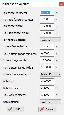
Member Definition Dialog
Generate Plates Methodology:
- Depth of Web (D) = Maximum
Span Length (all girders in a span) (L) /X rounded up to nearest multiple of 2
in. with a minimum of 24 in.
For example, straight continuous beam with L = 148 ft:
D = 148x12/35 = 50.74 in => 52 in.
Use maximum web depth required for all spans and all girders (constant depth throughout).
- Thickness of Web (tw) =
D/150, rounded up to nearest multiple of 1/16th in. with a minimum of 1/2 in.
For example, D = 52 in: tw = 52/150 = 0.35 => 1/2 in.
If web thickness changes are due to different span lengths, use the thicker web to 25% of the length of the adjacent span with the thinner web (do not change web thickness at pier)
- Width of Flanges, bf = D/6 rounded up to the nearest user specified width increment, with a minimum of 12 in. For example, D = 74 in: bf = 74/6 = 12.33 in. => 13 in. (for width increment = 1 in.)
- Thickness of flanges, tf =
maximum of [ Width of Flange (bf)/24] and [tf >= 1.1*Web Thickness tw ],
rounded up to nearest multiple of 1/8 in. with a minimum of 1/2 in. For
example, bf = 13 and tw = 0.5: tf= max( 13/24 = 0.542 and 1.1*0.5 = 0.55) =>
5/8 in.
If flange dimensions change due to different span lengths, use the larger area flange to 25% of the length of the adjacent span with the smaller flange area (do not change flange dimensions at pier).
- Use Grade 50 as a default material.
- Automatically place "cuts" in flange plates at 25% of span on either side of interior supports, even if plates do not change.
Overview of Design Optimization
The Design Optimization process will start with the member definition as described in the Member Definition dialog. In the case of top and bottom flanges this will be the thickness and start width. These can be thought of as the minimum thickness and minimum width respectively. Two additional fields on the same dialog, max thick and max width, will set the upper bounds for each dimension as the Design Optimization process sizes the plates.
Webs starting information will be the web height and thickness plus any transverse and/or longitudinal stiffeners that may have been added to the model.
Flange Plate Optimization-
The general process used by the flange plate Design Optimization process is as follows. Note that internally LEAP Bridge Steel generates a master available plate list that is sorted by area. All plates in the list satisfy specification b/t ratios.
- Perform code checking for each load combination defined in the Loads dialog. The code checking will be based on the Articles/equations listed in the Specification Checks table below.
- If a Specification failure
occurs for an article/equation, flag the failure type as described in the table
below and perform the specified action.
- Leap Bridge Steel will eliminate all plates in the master plate list that fall outside the plate width and thickness and maximum width and maximum thickness that are entered for the respective flange plates. This adjusted plate list is again sorted by plate area.
- Using the recomputed plate area look up a new plate in the adjusted plate list. The new plate will be the first one in the list with area that is greater than or equal to the previously computed area
Repeat this process until a satisfactory top and/or bottom flange plate is obtained or the maximum size of the top and/or bottom flange plates are reached.
Flange Specification Checks:
This table shows the specification articles and equations that are checked as part of the design optimization process along with the action that the process takes for each when the check fails.
| Spec Failure | Description | Resulting Action |
| 6.10.1.6-1 | Tension Flange Lateral Bending Stress Check | Increase Size of Tension Flange |
| 6.10.1.6-1 | Compression Flange Lateral Bending Stress Check | Increase Size of Compression Flange |
| 6.10.2.2-1 | Compression flange width/thickness ratio | Increase Size of Compression Flange |
| 6.10.2.2-1 | Tension flange width/thickness ratio | Increase Size of Tension Flange |
| 6.10.2.2-2 | Compression flange min width | Increase Size of Compression Flange |
| 6.10.2.2-2 | Tension flange min width | Increase Size of Tension Flange |
| 6.10.2.2-3 | Compression flange min thickness | Increase Size of Compression Flange |
| 6.10.2.2-3 | Tension flange min thickness | Increase Size of Tension Flange |
| 6.10.2.2-4 | Flange Moment of Inertia Ratio | Increase Size of Tension Flange |
| 6.10.3.2.1-1 | Compression flange yielding | Increase Size of Compression Flange |
| 6.10.3.2.1-2 | Compression Flange Strength Limit State | Increase Size of Compression Flange |
| 6.10.3.2.1-3 | Web Bend-Buckling | Increase Size of Compression Flange |
| 6.10.3.2.2-1 | Tension flange yielding | Increase Size of Tension Flange |
| 6.10.3.2.3-1 | Compression flange yielding | Increase Size of Compression Flange |
| 6.10.3.2.3-1 | Tension flange yielding | Increase Size of Tension Flange |
| 6.10.3.2.4 | Stress in Concrete Deck | Warning Message |
| 6.10.4.2.2-1 | Composite top flange stress | Increase Size of Top Flange |
| 6.10.4.2.2-2 | Composite bottom flange stress | Increase Size of Bottom Flange |
| 6.10.4.2.2-3 | Non-composite top flange stress | Increase Size of Top Flange |
| 6.10.4.2.2-3 | Non-composite bottom flange stress | Increase Size of Bottom Flange |
| 6.10.4.2.2-4 | Compression Flange Stress Requirement | Increase Size of Compression Flange |
| 6.10.7.1.1-1 | Tension flange Strength Limit State | Increase Size of Tension Flange |
| 6.10.7.2.1-1 | Compression flange check | Increase Size of Compression Flange |
| 6.10.7.2.1-2 | Tension flange check | Increase Size of Tension Flange |
| 6.10.7.3-1 | Ductility | Increase Size of Top Flange |
| 6.10.8.1.1-1 | Compression Flange Strength Limit State | Increase Size of Compression Flange |
| 6.10.8.1.2-1 | Tension flange Strength Limit State | Increase Size of Tension Flange |
| 6.10.8.1.3-1 | Continuously Braced Compression Flange Check | Increase Size of Compression Flan |
Plate Library:
This table shows the thicknesses that the design optimization process progresses through when incrementing top and bottom flange plates.
| English Plate Thickness | Decimal | Soft Conversion Metric Plate Thickness |
| 5/16 | 0.3125 | 8 |
| 3/8 | 0.375 | 10 |
| 7/16 | 0.4375 | 11 |
| 1/2 | 0.5 | 13 |
| 9/16 | 0.5625 | 14 |
| 5/8 | 0.625 | 16 |
| 11/16 | 0.6875 | 17 |
| 3/4 | 0.75 | 19 |
| 13/16 | 0.8125 | 21 |
| 7/8 | 0.875 | 22 |
| 15/16 | 0.9375 | 24 |
| 1 | 1 | 25 |
| 1-1/8 | 1.125 | 29 |
| 1-1/4 | 1.25 | 32 |
| 1-3/8 | 1.375 | 35 |
| 1-1/2 | 1.5 | 38 |
| 1-5/8 | 1.625 | 41 |
| 1-3/4 | 1.75 | 44 |
| 1-7/8 | 1.875 | 48 |
| 2 | 2 | 51 |
| 2-1/4 | 2.25 | 57 |
| 2-1/2 | 2.5 | 64 |
| 2-3/4 | 2.75 | 70 |
| 3 | 3 | 76 |
| 3-1/4 | 3.25 | 83 |
| 3-1/2 | 3.5 | 89 |
| 3-3/4 | 3.75 | 95 |
| 4 | 4 | 102 |
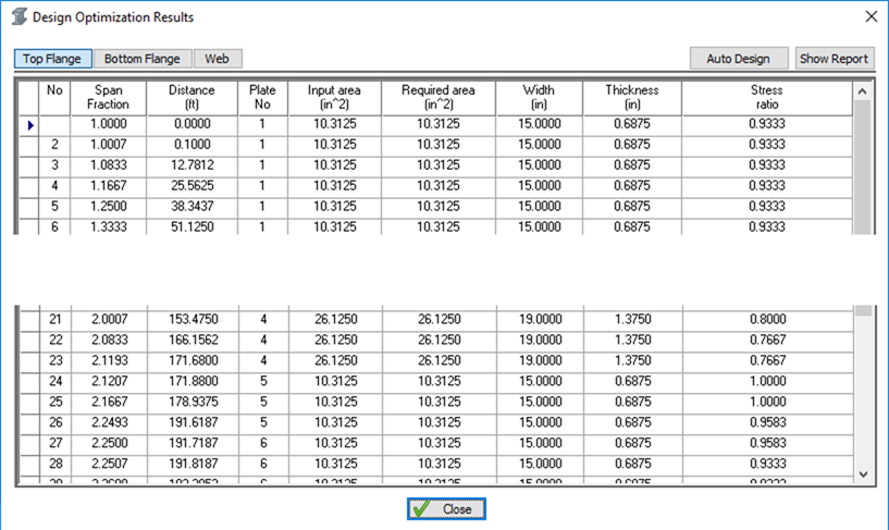
Flange Design Optimization Results:
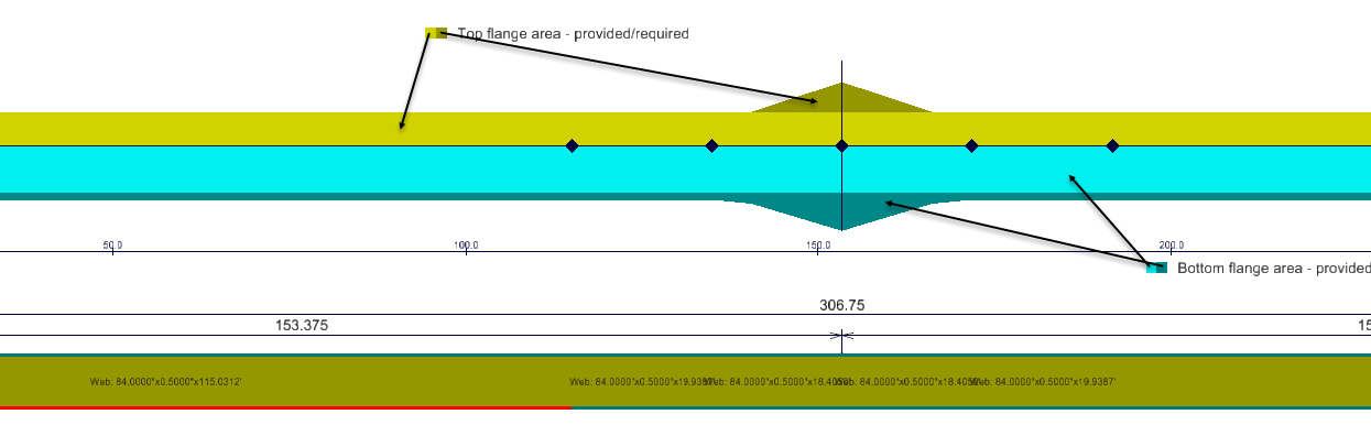
Flange optimization results are shown in both graphical
and report form. Graphical results will appear if the Plot results in elevation
view box is checked ( )when the Member element is set
to Flange. A description of the graphic results display is shown below. The
adequacy of the flanges is represented by the flange area. Plate sizes that
correspond to the flange areas are shown in the flange optimization report. In
cases where the required area exceeds the actual area either the plate
thickness or width can be changed.
)when the Member element is set
to Flange. A description of the graphic results display is shown below. The
adequacy of the flanges is represented by the flange area. Plate sizes that
correspond to the flange areas are shown in the flange optimization report. In
cases where the required area exceeds the actual area either the plate
thickness or width can be changed.
If it is desired to use the computed top and bottom flange
results in the model definition, the Auto Design button ( ) on the Results dialog can be
used. This will cause the flange plate sizes (width and thickness) in the
Member definition grid to be updated.
) on the Results dialog can be
used. This will cause the flange plate sizes (width and thickness) in the
Member definition grid to be updated.
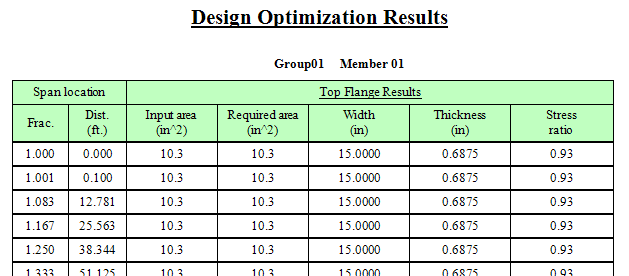
The results of the design optimization process are shown in the report shown below that is generated when the Design results button is pressed.
The report shows, on a POI by POI basis, the flange area based on the plate sizes entered on the member definition screen. The required flange plate area based on the design optimization process is shown next. The required area, width and thickness are shown in red for Instances where the input flange plate did not satisfy demand. The performance ratio for the optimized design is also shown.
Given the information in the Design Optimization Report, the model can be updated with revised plate sizes and re-optimized until an acceptable design results.
The required area is optionally plotted in the elevation view if the "Plot results in elevation view" option is checked.
Web Plate Optimization-
The general process used by the web plate design optimization process is as follows.
- Perform code checking for each load combination defined in the Loads dialog. The code checking will be based on the Articles/equations listed in the Specification Checks table below.
- Start with the specified web height and web thickness, iterating the thickness in 1/16 in increments up to the maximum web thickness. Additionally, any transverse or transverse/longitudinal stiffeners are taken into account.
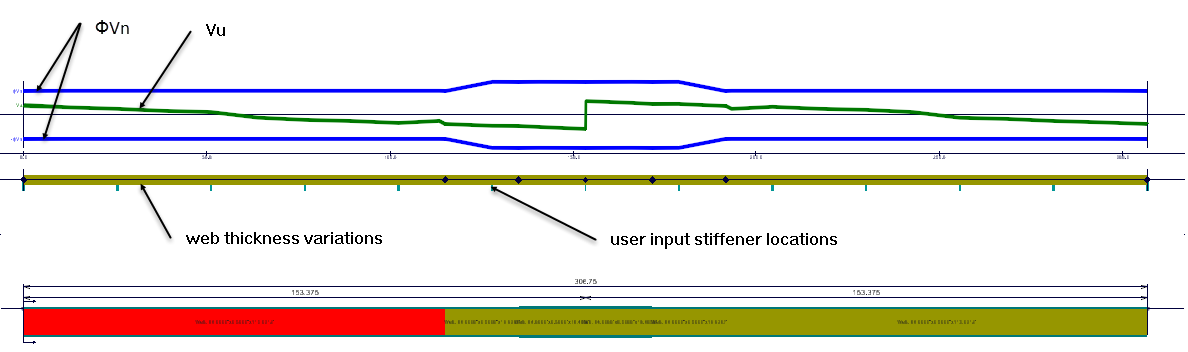
- Determine if the demand (Vu) exceeds the resistance (ΦVn)
- If demand is less than the resistance and the web thickness has not exceeded the input maximum thickness, the solution is reported as the Required solution (tw and d0) in the Design Optimization Results dialog. If the computed web thickness also qualifies as an unstiffened web no required stiffener spacing (d0) is reported. Otherwise a required stiffener spacing to satisfy demand is reported.
- In addition to generating
the required result with respect to the input data, the web optimization
process will also compute and report the following as additional information
for the user:
- the web thickness that will work as unstiffened
- whether longitudinal stiffeners are required (i.e. 150 < D/tw 300)
- the web thickness that will work for the maximum transverse stiffener spacing for transverse stiffening only
- the web thickness that will work for the maximum transverse stiffener spacing if the web is longitudinally stiffened.
Web Specification Checks:
This table shows the specification articles and equations that are checked as part of the web design optimization process along with the action that the process takes for each when the check fails.
| Spec Failure | Description | Resulting Action |
| 6.10.2.1.1-1 | Min thickness of web without longitudinal stiffeners | Add longitudinal stiffener (last iteration ?) |
| 6.10.2.1.1-2 | Min thickness of web without longitudinal stiffeners | No solution - web fails (last iteration) |
| 6.10.3.3-1 | Shear in stiffened webs | Increase web thickness |
| 6.10.5.3-1 | Shear check Strength limit state | Increase web thickness |
| 6.10.9.1-1 | Shear check Strength limit state | Increase web thickness |
Web Design Optimization results
Web optimization results are shown in both graphical and
report form. Graphical results will appear if the Plot results in elevation
view box is checked () when the Member element is set
to Web. A description of the graphic results display is shown below. Note that
the results shown are for the Required results as described in the report
section below.
If it is desired to use the computed required results in
the model definition, the Auto Design button () on the Results dialog can be
used. This will cause the web plate sizes (thicknesses) in the Member
definition grid to be updated.
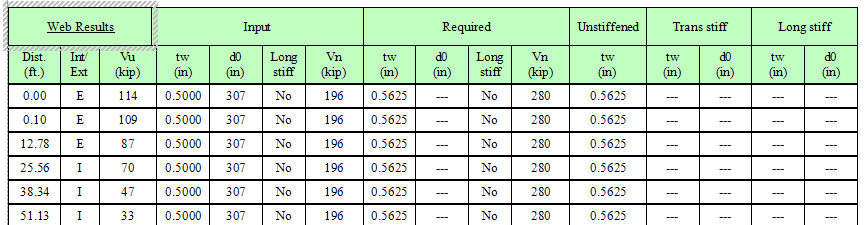
Reported results for the web optimization process are described below. The report is generated when the Show Report button is pressed on the Design Optimization Results dialog.
- POI distance
- Flag indicating the POI is in an end or interior stiffener panel
- Shear demand Vu
- Input
- Required
- Final web thickness (tw) produced by the optimization process
- If a web must be stiffened, the required stiffener spacing (d0) based on the final web thickness. If the web thickness works as unstiffened, this field will be blank
- If a longitudinal stiffener is required relative to the top flange, the distance from the top flange to the stiffener (ds) will be shown. If no longitudinal stiffener is required, this field will be blank
- If a longitudinal stiffener is required relative to the bottom flange, the distance from the bottom flange to the stiffener (ds) will be shown. If no longitudinal stiffener is required, this field will be blank.
- The computed required resistance (ΦVn)
- Unstiffened (informational)
- Trans Stiff (transversely
stiffened)
- This is the computed web thickness (tw) based on using the maximum stiffener spacing for transversely stiffened girder (3D or 1.5D) shown in the next column
- This is the maximum allowable stiffener spacing 9d0) to qualify a web as stiffened when no longitudinal stiffener is present (computed as 3.0D for interior panels and 1.5D for exterior panels).
- Long Stiff
(longitudinally stiffened)
- This is the computed web thickness (tw) the based on using the maximum stiffener spacing for longitudinally stiffened girder (1.5D) in the next column.
- This is the maximum allowable stiffener spacing (d0) to qualify a web as stiffened when a longitudinal stiffener is present (computed as 1.5 D for both interior and exterior panels)